Fundamentals of Refrigeration and Air-Conditioning (course ) 2
2.1 Basic vapour compression cycle
A liquid boils and condenses – the change between the liquid and
gaseous states – at a temperature which depends on its pressure,
within the limits of its freezing point and critical temperature. In
boiling it must obtain the latent heat of evaporation and in condensing
the latent heat must be given up again.
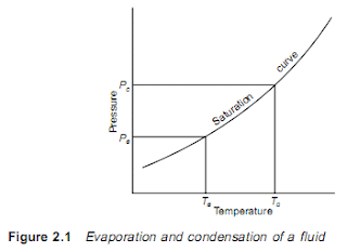
The basic refrigeration cycle (Figure 2.1) makes use of the boiling
and condensing of a working fluid at different temperatures and,
therefore, at different pressures.
Heat is put into the fluid at the lower temperature and pressure
and provides the latent heat to make it boil and change to a vapour.
This vapour is then mechanically compressed to a higher pressure
and a corresponding saturation temperature at which its latent heat
can be rejected so that it changes back to a liquid.
The total cooling effect will be the heat transferred to the working
fluid in the boiling or evaporating vessel, i.e. the change in enthalpies
between the fluid entering and the vapour leaving the evaporator.
For a typical circuit, using the working fluid Refrigerant 22,
evaporating at – 5°C and condensing at 35°C, the pressures and
enthalpies will be as shown in Figure 2.2.
Enthalpy of fluid entering evaporator = 91.4 kJ/kg
Enthalpy of saturated gas leaving evaporator = 249.9 kJ/kg
Cooling effect = 249.9 – 91.4 = 158.5 kJ/kg
A working system will require a connection between the condenser
and the inlet to the evaporator to complete the circuit. Since these
are at different pressures this connection will require a pressure-
reducing and metering valve. Since the reduction in pressure at
this valve must cause a corresponding drop in temperature, some
of the fluid will flash off into vapour to remove the energy for this
cooling. The volume of the working fluid therefore increases at the
valve by this amount of flash gas, and gives rise to its name, the
expansion valve. (Figure 2.3.)
2.2 Coefficient of performance
Since the vapour compression cycle uses energy to move energy,
the ratio of these two quantities can be used directly as a measure
of the performance of the system. This ratio, the coefficient of
performance, was first expressed by Sadi Carnot in 1824 for an
ideal reversible cycle, and based on the two temperatures of the
system, assuming that all heat is transferred at constant temperature
(see Figure 2.4). Since there are mechanical and thermal losses in
a real circuit, the coefficient of performance (COP) will always be
less than the ideal Carnot figure. For practical purposes in working
download the full (lessons 1&2) :
http://www.multiupload.com/ABRND8WN56


Comments